EN
EN



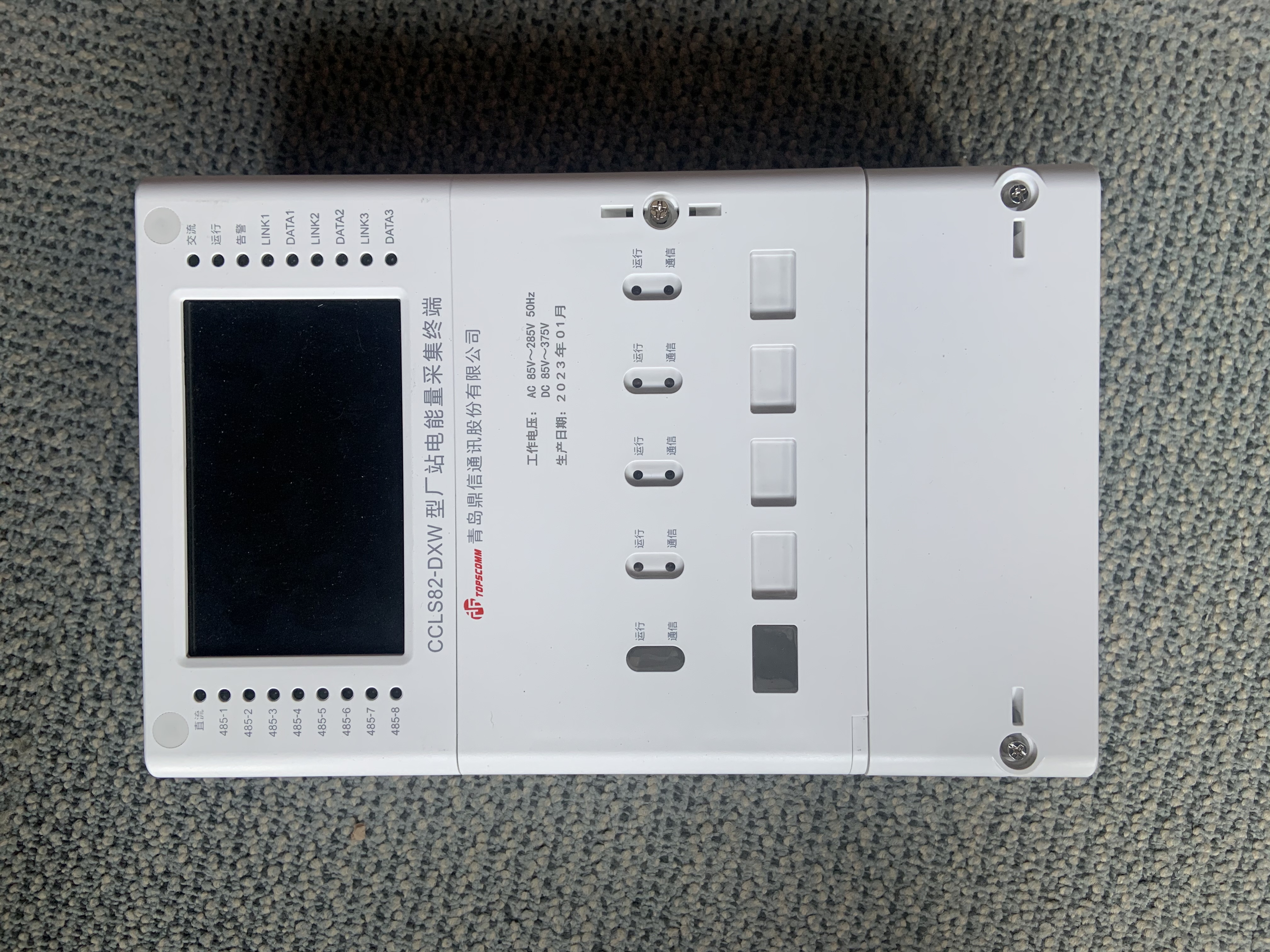
Power utilities rely on advanced data collection and communication infrastructure to monitor grid performance, manage demand, and ensure service reliability. Real-time data throughput testing on a plc module for dcu is critical to validate that communication networks can handle peak loads and maintain signal integrity under operational stress. Testing procedures ensure that programmable logic controller integration for data collection unit systems meet performance expectations before deployment in production environments.
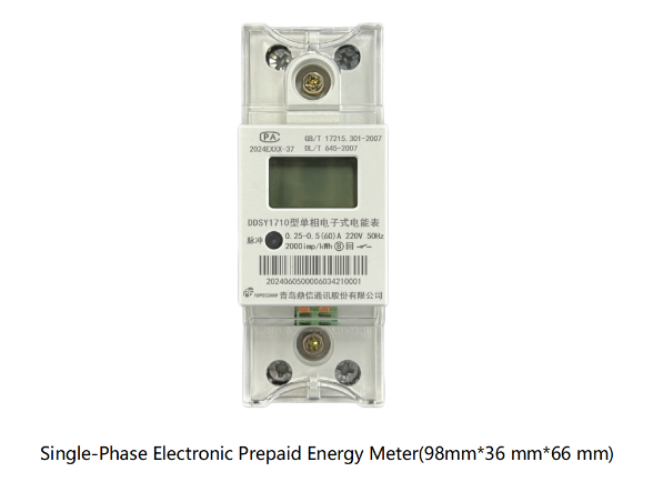
Testing frameworks must simulate real-world conditions including demand response signals, meter data collection, and system-to-system communication events. The dcu communication interface module serves as the bridge between field devices and central monitoring systems, making throughput validation a fundamental requirement. This article explores the methodologies, tools, and best practices utilities use to verify that their plc hardware compatibility requirements for dcu systems are satisfied before full-scale implementation.
Understanding Real-Time Data Throughput Requirements
Defining Throughput in Utility Environments
Real-time data throughput refers to the volume of data packets a dcu communication interface module can process per second while maintaining acceptable latency and error rates. In power utility applications, throughput directly impacts the speed at which meter readings, alarm signals, and control commands propagate through the network. A programmable logic controller integration for data collection unit must support predictable, measurable data flow rates to prevent bottlenecks during peak consumption periods or emergency events.
Throughput capacity determines how many endpoints a single plc module for dcu can service simultaneously. When utilities scale their networks, they must understand whether to expand hardware capacity, optimize message protocols, or implement load-balancing strategies. Understanding baseline throughput requirements before deployment prevents costly retrofits and service disruptions.
Compliance and Industry Standards
Industry standards such as IEC 61850 and DLMS/COSEM establish baseline expectations for utility data communication. These standards define message formats, response times, and acceptable data loss thresholds. Plc hardware compatibility requirements for dcu systems must align with these standards to ensure interoperability across multiple vendors and system generations.
Utilities also follow regional regulations that mandate specific performance metrics and failover response times. Testing against these standards provides documented evidence that systems comply with regulatory expectations and can maintain service during grid disturbances.
Testing Methodology and Practical Approach
Load Simulation and Protocol Testing
Testing begins with establishing baseline conditions using software-based load generators that create synthetic data traffic mimicking real field devices. Engineers configure these generators to send messages at intervals matching actual production patterns, including peak demand windows and off-peak periods. A dcu communication interface module undergoes testing at 50%, 75%, and 100% of rated capacity to identify degradation curves and breaking points.
Protocol testing validates that the plc module for dcu correctly interprets all supported message types, handles protocol errors gracefully, and maintains session state during network interruptions. Testing teams transmit malformed packets, duplicate messages, and out-of-sequence data to verify error-handling robustness. These stress scenarios ensure that programmable logic controller integration for data collection unit systems remain stable under adverse conditions.
Hardware and Interface Validation
Plc hardware compatibility requirements for dcu systems demand comprehensive testing of physical interfaces, processor performance, and memory management. Engineers measure CPU utilization, memory allocation, and thermal characteristics under sustained load. Temperature monitoring ensures the module remains within operational limits even during continuous maximum-throughput periods.
Ethernet and serial port interfaces undergo testing with legitimate and corrupted traffic patterns. Network cables, connector types, and signal integrity are verified to detect issues that could degrade performance in harsh utility environments. Testing also includes hot-swap scenarios where communications continue during module replacement, confirming high-availability design effectiveness.
Measurement Tools and Performance Metrics
Network Monitoring and Data Capture
Utilities employ packet-capture tools and protocol analyzers to observe actual traffic patterns flowing through the dcu communication interface module. These tools reveal message timing, payload sizes, and error rates in precise detail. Wireshark, SNMP monitors, and vendor-specific diagnostic platforms provide real-time dashboards showing throughput, latency percentiles, and packet loss statistics.
Baseline metrics capture normal operating conditions for comparison against degraded or stressed scenarios. When a plc module for dcu exhibits unexpected behavior, engineers compare current traffic patterns against these baselines to isolate whether the issue is a capacity limit, configuration problem, or hardware fault. This comparative analysis accelerates troubleshooting and confirms whether programmable logic controller integration for data collection unit systems are functioning as designed.
End-to-End Latency and Response Time Analysis
Response time testing measures the delay between sending a request and receiving the corresponding response through the plc hardware compatibility requirements for dcu systems. Utilities define acceptable latency windows—often 100 to 500 milliseconds for routine data collection and shorter windows for critical control signals. Testing tracks latency percentiles (95th, 99th) rather than only average times, since peak delays matter most for reliability.
Tools inject timestamped test packets and measure round-trip delays through the dcu communication interface module under various load conditions. When latency exceeds thresholds, engineers investigate whether the module, network, or endpoint devices are responsible. Performance testing also validates that latency remains acceptable even when competing traffic types share the same communication path.
Practical Deployment Validation
Field Trial and Staging Environment Testing
Before full production rollout, utilities deploy the plc module for dcu in controlled staging environments that mirror production architecture. These trials connect actual field devices, backend systems, and communication networks to replicate real operational conditions more closely than laboratory simulations. Staging tests verify that programmable logic controller integration for data collection unit systems integrate correctly with legacy equipment and modern applications.
Utilities gradually increase data volume in staged environments, documenting performance metrics at each step. This incremental approach helps identify capacity limits before they impact real customers. Testing teams also validate failover behaviors, system recovery after communication outages, and data consistency across multiple systems.
Continuous Monitoring Post-Deployment
After deployment, utilities maintain ongoing performance monitoring to ensure that plc hardware compatibility requirements for dcu systems continue to meet expectations. Production data from the dcu communication interface module reveals trending information about growth patterns, peak utilization, and emerging bottlenecks. This historical data informs future capacity planning and hardware upgrade decisions.
Anomalies in throughput patterns trigger investigation to detect early signs of module degradation, network congestion, or misconfiguration. Alerting thresholds ensure that performance problems surface before they cascade into service failures. Continuous monitoring transforms one-time testing into an ongoing assurance process that maintains system reliability throughout the module's operational lifetime.
FAQ
What throughput capacity should a plc module for dcu support for a medium-sized utility?
Medium-sized utilities typically require dcu communication interface module capacity between 1,000 and 5,000 messages per second, depending on meter density and reporting frequency. A programmable logic controller integration for data collection unit supporting 2,000 to 3,000 messages per second accommodates most demand-responsive applications while providing 40–50% headroom for peak load scenarios. Actual requirements depend on the number of endpoints, data refresh intervals, and historical growth rates specific to each utility network.
How do utilities validate plc hardware compatibility requirements for dcu systems in lab versus production settings?
Lab testing isolates the plc module for dcu and simulates traffic using software generators under controlled conditions, while production validation uses real field devices, actual network paths, and mixed workload patterns. Lab testing identifies throughput limits and protocol correctness, whereas production testing reveals integration issues, timing interactions, and real-world variability that simulators cannot fully replicate. Best practice involves thorough lab testing followed by staged field trials before full rollout.
What happens if a plc module for dcu fails throughput testing?
If the dcu communication interface module fails testing, engineers investigate root causes—such as insufficient processor resources, protocol implementation bugs, or network configuration issues—and determine whether fixes are possible through software updates or require hardware replacement. Programmable logic controller integration for data collection unit systems may need optimization, configuration adjustment, or retirement in favor of higher-capacity alternatives. Failed modules must never proceed to production until they demonstrate acceptable performance under representative stress conditions.